
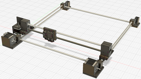
A0-size plotter build from 3d printed components
Download Build Manual
The link below points to a PDF file which describes the individual components of this plotter. These components are the 3d printed plastics, the Arduino and RAMPS hardware, the power supply, the emergency stop, the software which runs on the Arduino and the Python application. In addtion the development environments for these two types of software are described from how to install them to the required settings and needed packages for your own software development.
Plotter build manual
If you want to build this plotter: you can download the full package (stl files, Arduino SW, Python code) from pinshape.
Download
Description
The plotter is build with 1 meter rods, but you can make it smaller as you wish. The software is 'as is'. The manual (PDF file) provides detailed information about how to build the plotter, which additional rods, bolts, etc are needed as well as which Arduino and RAMPS board is used to control the stepper motors. The interconnections (mechanical as well as electrical) is described. Also the download and install of the required Arduino and Python development environment is described in detail. The source code is added in the zip file.
This plotter can be used to create large (cheap) plots, but it could also be used by DIY learners to find out how the software is partitioned and why this is done is this way. There are of course many different ways to create this, it is just a choice to have the user interface software in Python and the HW control software handled by an Arduino.
The Python code includes a simple but practical 'simulator', which is shows the plot result as a drawing on your computer. This enables it to practice with the software without wasting paper.
I do not claim that the software is error free. If it isn't than the issue is not known by me (otherwise it would have been fixed). So the examples do work as expected. You can use this software as a starting point for further experiments. You can also change the simulator to be a 'live' simulator which actually shows the plot movements. Same applies to the Arduino graphical LCD, I did not use it, but you could extend the software to make use of it. So this 'example' of HW and SW could be used as a starting point for further exploration / learning / fun / ....